Bone torque and flex weights
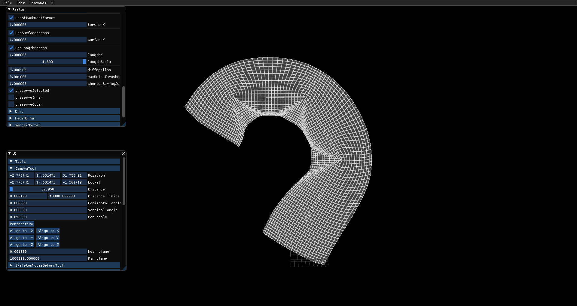
Today I added some controls to my spring force solver. My goal is to have the spring solver "always-on" (updating the mesh once per frame based on the spring forces), but whenever I'd try letting the solver run continuously, the spring forces would eventually skew too much to be considered usable or stable. So a mesh skinned with LBS may look like this:
And using the results from LBS as the initial state, this is how it looks after a few rounds of the solver:
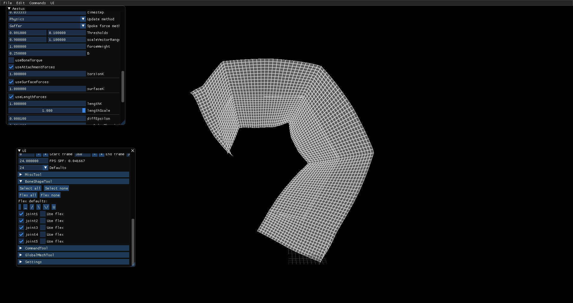
The middle regions look OKish, but vertices near the root and the leaf have distorted considerably. Eventually the spring forces stop altering the mesh and it looks like this:
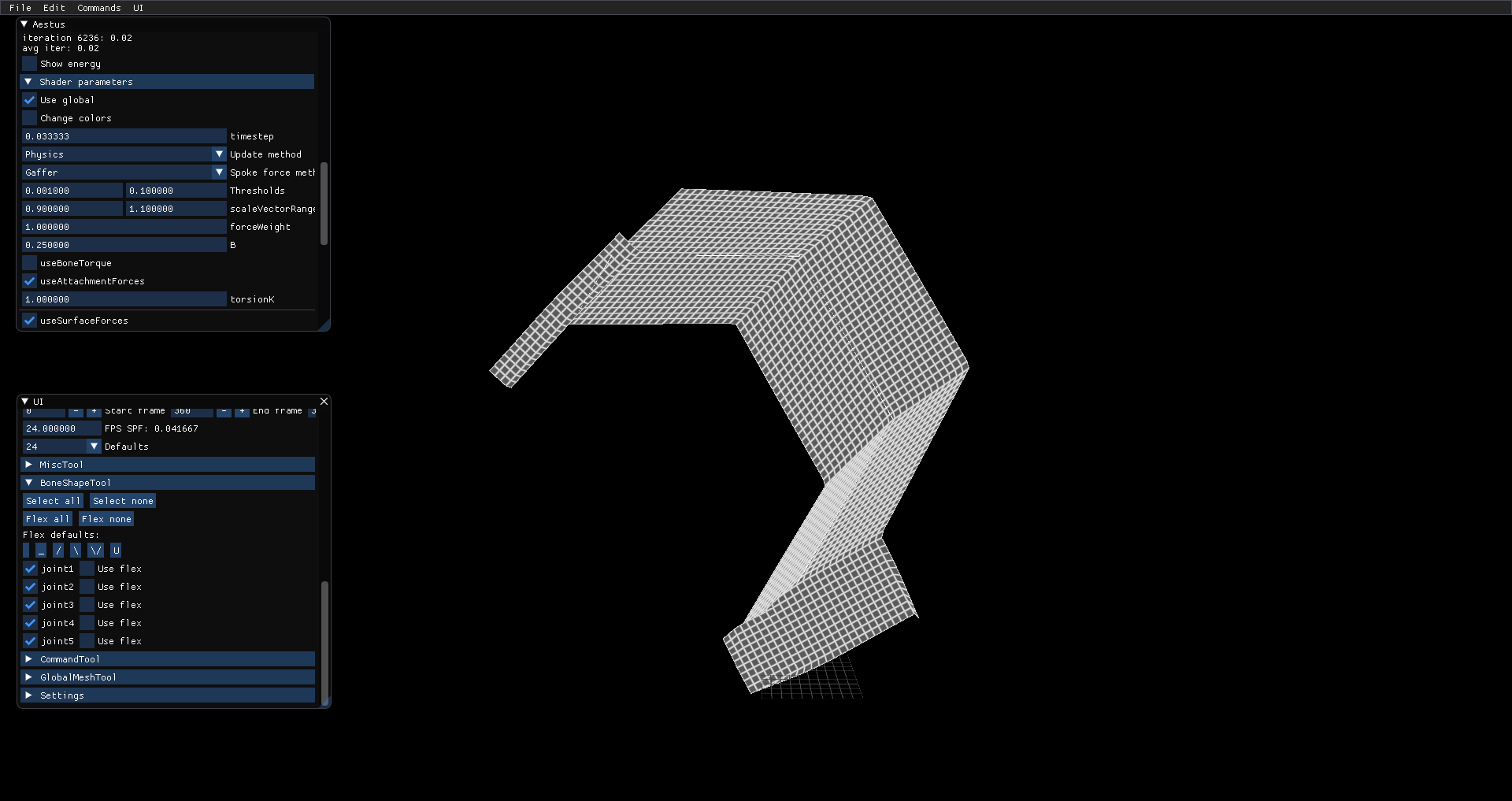
So it definitely needs some help. To help stabilize the solver, I considered 2 choices:
- Modify the solver so vertices along the bone can have varying flexibility. For example, vertices near the center of the bone should essentially retain their shape from LBS, while vertices near joints should be allowed to flex as much as possible.
- Try to add an additional force that counteracts the tendency for the mesh to skew.
Flex weights
I went with the first approach and implemented a few simple functions as flex weights. Each bone gets essentially a 1D, 1-channel float texture that the solver can use to accordingly weigh the computed force vectors. If the flex weight for certain vectors is 0, then this effectively adds static constraints to the solver and should prevent the skewing collapse. Here's what some of the flex functions look like:
Flex shape: U
Function: (float t) { return glm::pow(glm::abs<float>(t - 0.5f) * 2.0f, 2.0f); }
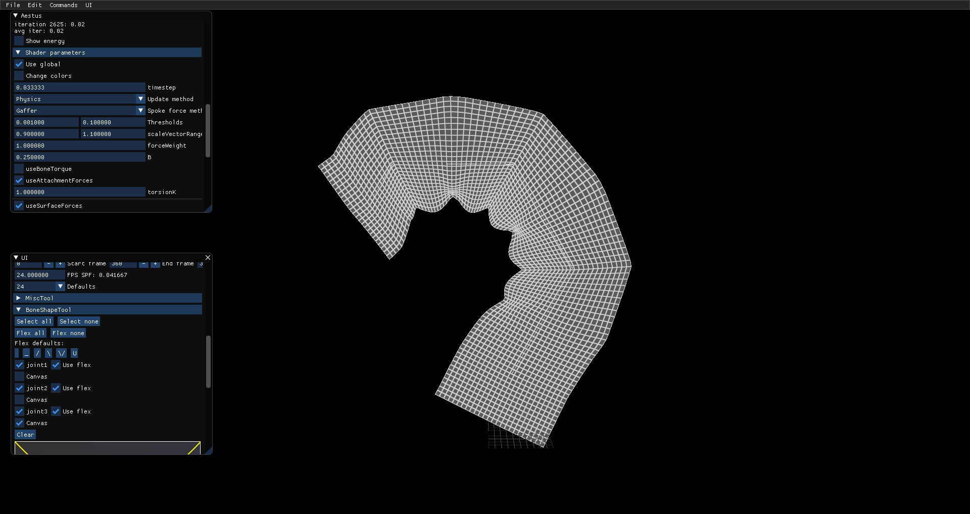
This represents a smooth change of flexibility across the bone, allowing the ends to vary but keeping the center rigid. "U" can see the effect this has on the mesh - since LBS introduces scale vector length changes, this makes the inner bends appear pinched as vertices in between the rigid regions deform to reduce the spring system's energy.
Flex shape: /
Function: (float t) { return t; }
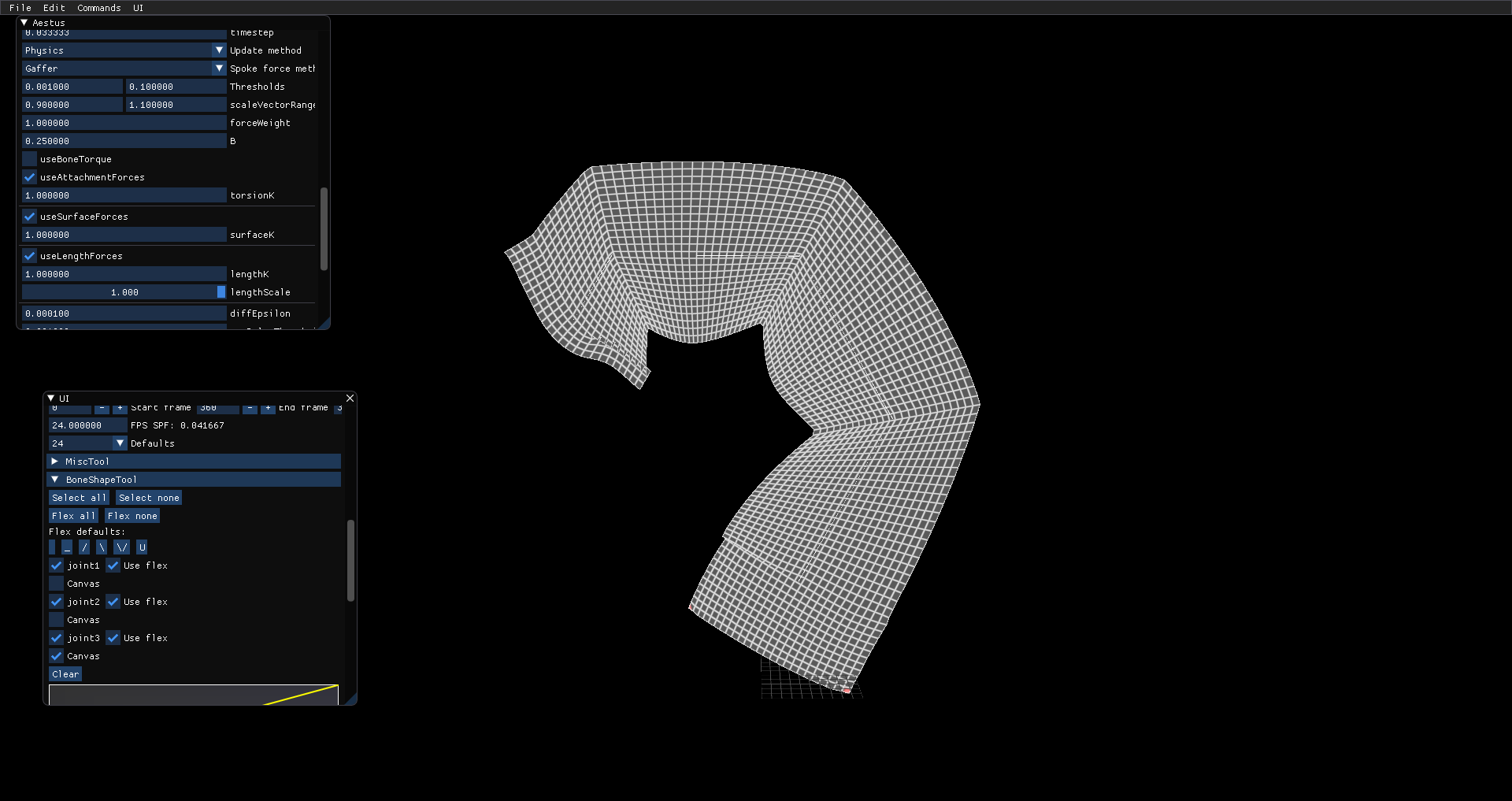
The linear flex function makes vertices at the start of a bone rigid, and more flexible as the mesh deforms. This looks a little more acceptable than the U function, but it makes for some strange deformations on the leaf joint's vertices.
Bone torque
With this approach, I'm setting the variable flexibility concept aside for a moment and focusing on what causes the skew during long runs. The spring force solver works by computing spring forces between adjacent vertices. One of those spring forces is a torsional force between adjacent scale vectors. So if the solver is left to run on its own, it will continue trying to minimize the scale vectors angles - there is no incentive to stop running if the angles can still be minimzed. This is how the skewing result happens.
I was counting on convergence checks to prevent this from happening, but that's less reliable for an always-on solver. Instead, I added a new torsion force. This one measures the angle between a scale vector and its connecting bone at bind, then when the solver is running, it computes a force to restore this angle.
Here's a look at the mesh with bone torque and stiffness coefficient=1
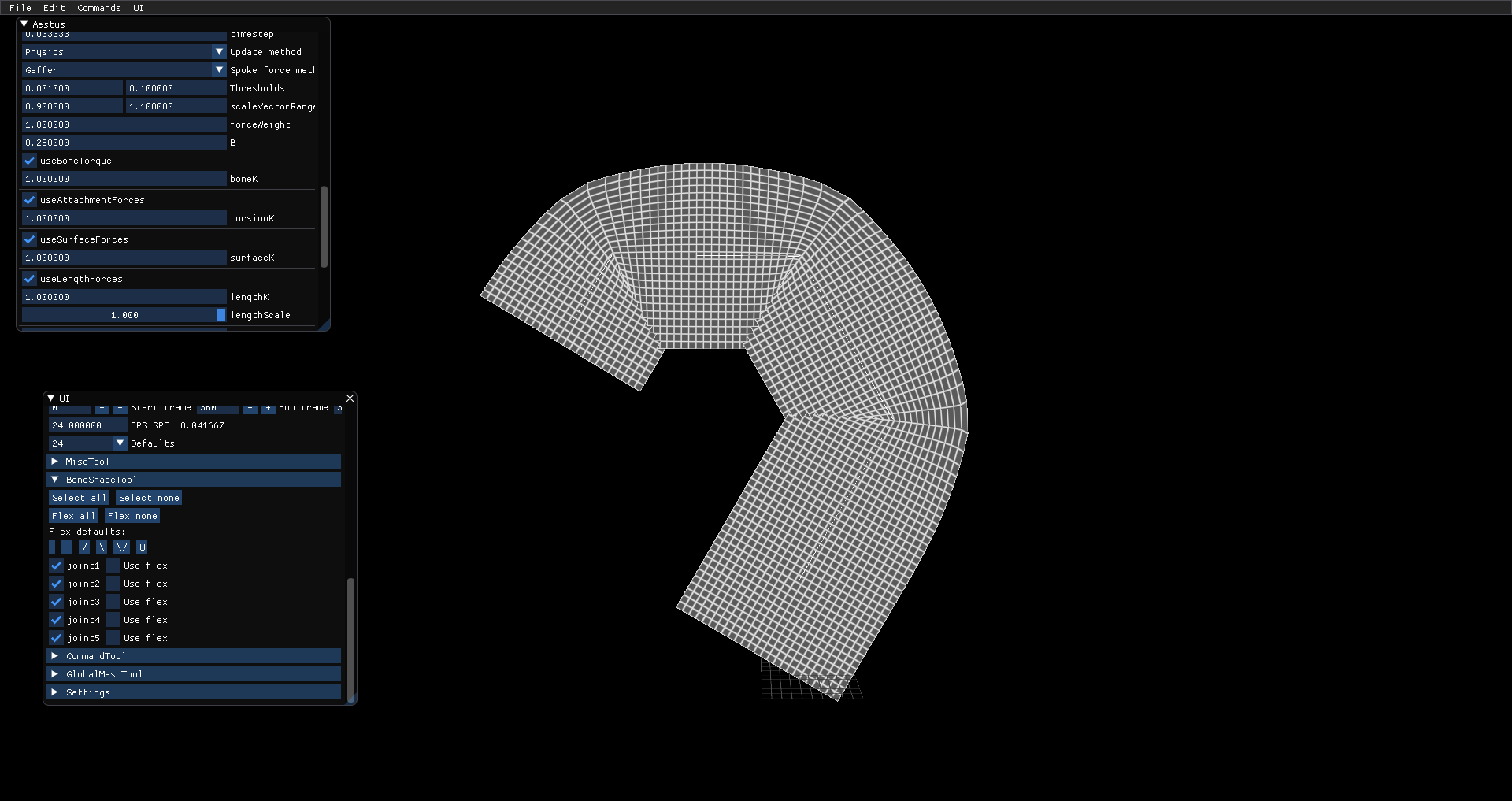
Not bad, maybe a little too rigid. The inner bends still look like they're overlapping, and there's some noticeable gaps on the outer bends. Here's the result using coefficient=0.1
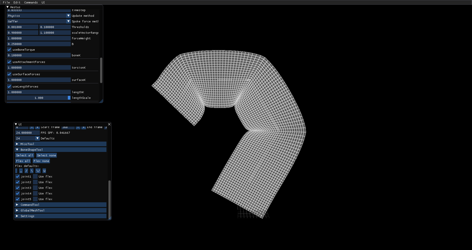
The outer bends look a little more pointy, but the inner bends have converged to nice pinches. The leaf joint's vertices are staying put, too!
Combined
Here are some figures with both flex weights and bone torque.
Bone coeff=0.1, flex U:
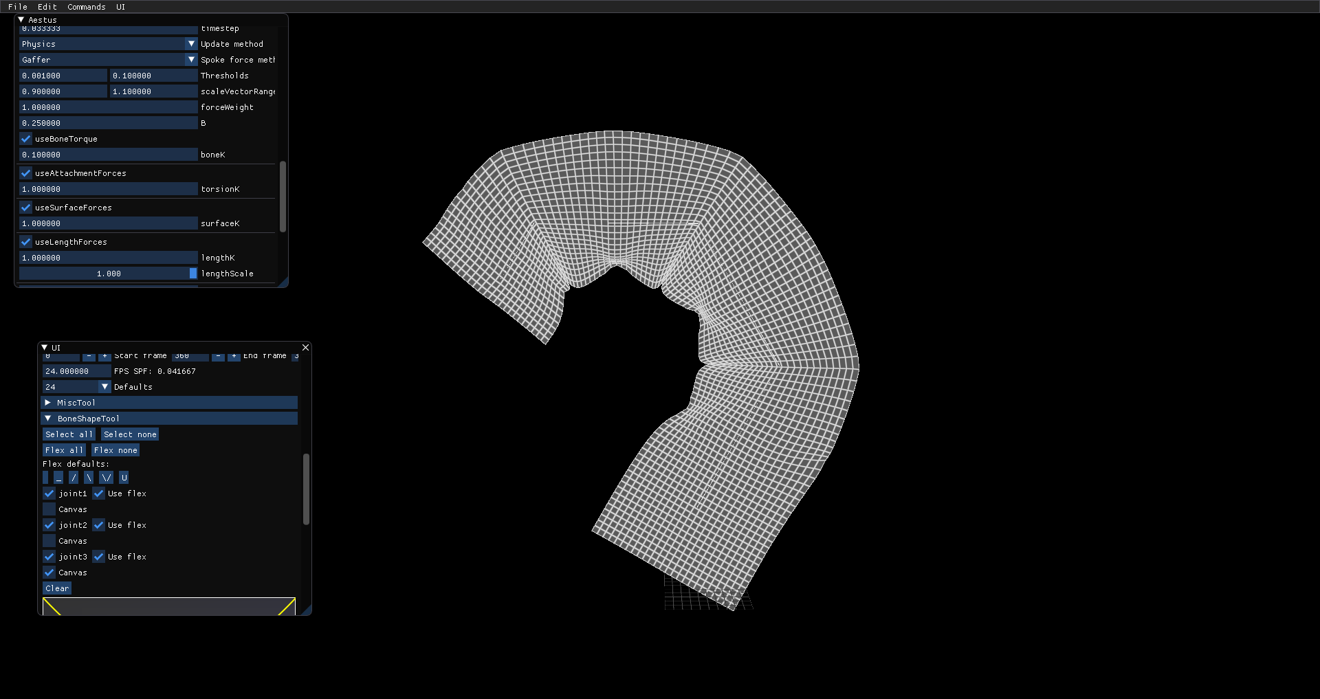
The pinching artifact returns, but looks a little more consistent and stylesque.
Bone coeff=0.1, flex /:
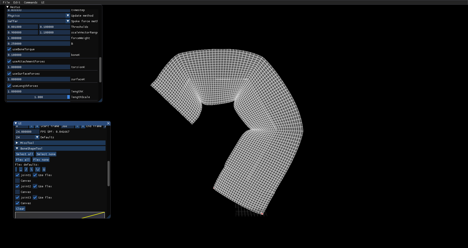
Bone coeff=0.1, flex \:
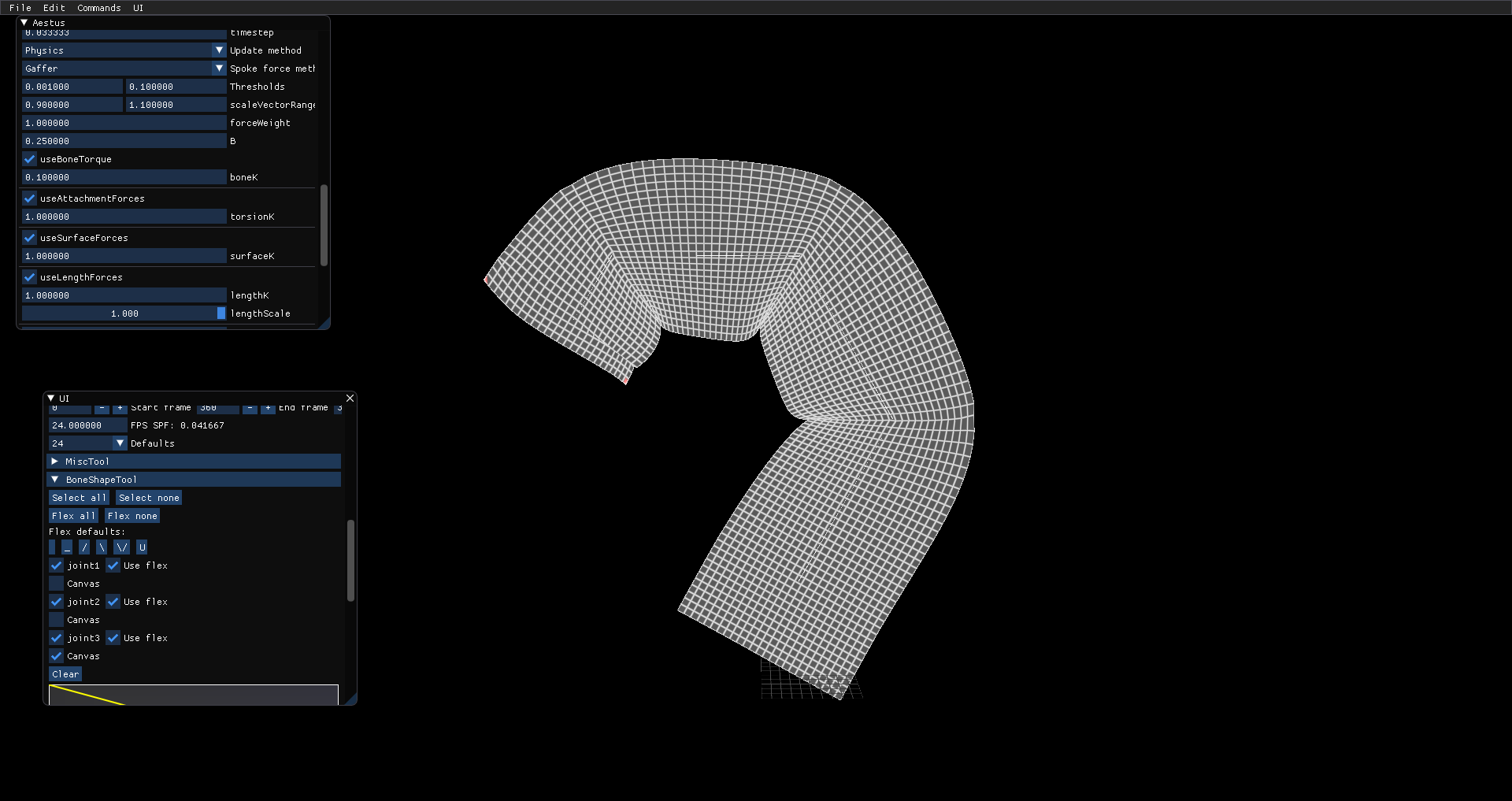
Subtle differences in the squish direction between / and \...