Attachment and rigidity

Glossary:
- ABCD: Attachment-based character deformation. Performs rigid skinning first, then deforms mesh vertices relative to a point of attachment on the skeleton.
- ARAP: As-rigid-as-possible surface modeling technique. Uses ROIs to define mesh deformation area. Switches between optimizing vertex positions and rotations to minimize cell energy until convergence.
- LSE: Laplacian surface editing. Uses ROIs to define mesh deformation area. Attempts to minimize changes to differential geometry.
- ROI: Region of interest on a mesh. Geometry is separated into solved (fixed in place) and unsolved (allowed to vary) groups. Solved groups include region boundaries to control the deformation size, and handles that can be deformed by the user to drive deformation. Unsolved groups include whatever geometry is contained within the boundaries.
This post concerns the abilities and limitations of ABCD. Namely, the attachment system produces the most visually appealing results when mesh skeletons are chains: single parent, single child.
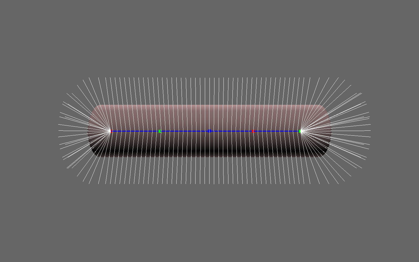
That's basically the poster child mesh of ABCD. Uniform thickness, a chain skeleton, and reasonable bone lengths. If the mesh and skeleton are bent, the default attachment scheme (direct projection onto nearest bone) fails considerably:
Why exactly is that a failure? Visually, it seems clear: the inner bend attachs to the skeleton strangely, leaving these large gaps in between adjacent attachment points. Intuitively, those attachment points should probably be close together. Why?
To deform a mesh vertex around a bending joint, ABCD has to find answers to a few questions:
- How close is the vertex to the bone? Is it within the bending joint's ROI?
- Is the vertex on the inner side of the bend, or the outer side?
- Is the bending joint on the parent side of the bone, or the child?
- How much is that joint bending, and along what axis?
Based on those answers, the vertex receieves a percentage of the joint's bend (including 0% if there's no influence). For this to smoothly deform the mesh, it requires some preservation of distances between attachment point, relative to the mesh. That is, if two mesh vertices are adjacent, then their attachment points should be, too. Or at least, they should have roughly the same distance between them. Watch what happens when ABCD skins the bent cylinder, both before and after smoothing the attachment points:
Pretty gross! Granted that the mesh doesn't seem well-suited for large outer bends, I was hopeful that ABCD would do a decent job uniformly straightening out the surface. For comparison, let's look at an inner bend:
Not a big surprise, but the mesh is better suited for inner bends. Still, it'd be nice to have more consistent behavior around the outer bend.
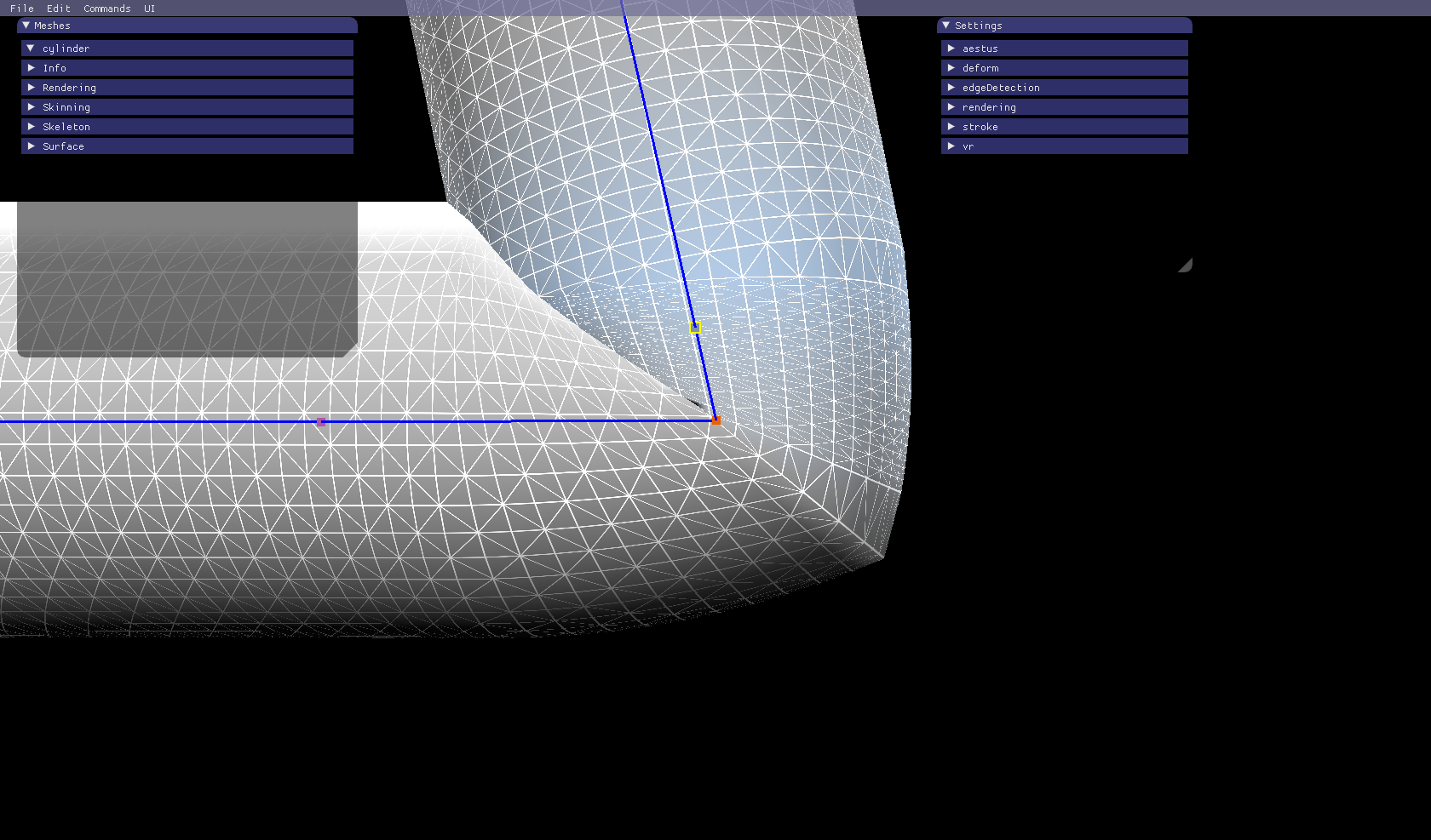
ABCD accommodates changes in bone length fairly well, but it's still problematic. Because of the linear mapping between attachment points and bone length, large bone length changes introduce their own discontinuities. The vertices along the bone are consistently-spaced with each other, and so are the vertices outside the bone's influence. But the boundary between them is too strong, and results in poor spacing:
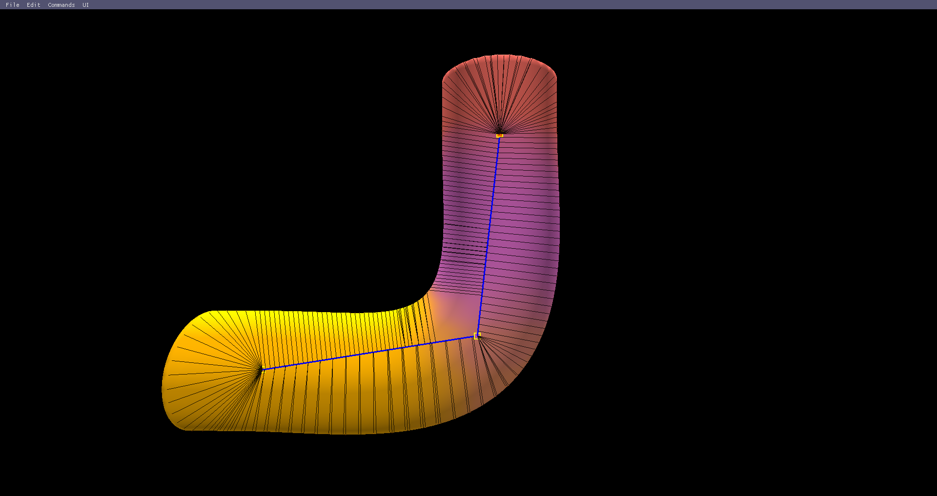
The same artifact could occur with large bone twists. Ultimately, the issue is this: ABCD behaves as though every vertex is mapped to exactly one bone in the skeleton. After rigid skinning with this data, it does what it can to smooth out the regions in between rigidly-skinned meshes. The issue gets even worse with more attached skeletons (joints with multiple children). Let's start with the LBS version of a pose:
Not pretty, but compared to this (ABCD, direct projection):
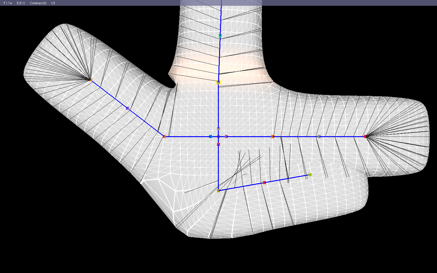
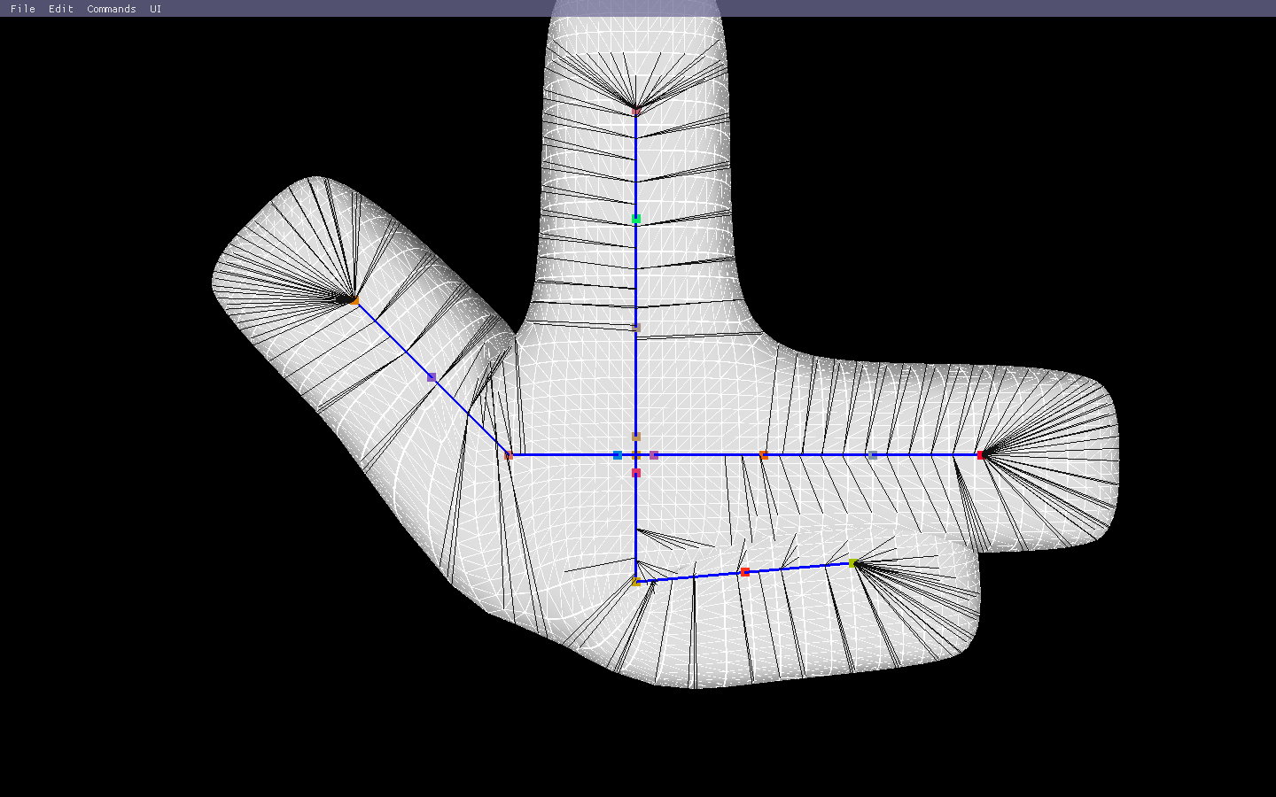
There are two bad artifacts: one in the upper left, and one in the lower left. They are both the result of the single bone vertex mapping. One way to try and "fix" them would be to edit the skeleton: uniformly extend the bone lengths around the root so the joints extend past the saddle-shaped regions, making the central region more rigid in the process. Better results, but only because the mesh is more rigid. If we want that region to deform smoothly, then we need another approach. What happens if we just try to smooth the attachment points a bit?
That's actually quite a bit better! Attachment quality definitely makes a pretty big difference in the skinning results. How does it handle a few more bends? Here's a comparison between ABCD and LBS. The biggest issue seems to be the skin weight quality I got from Maya (geodesic voxel @ 512 resolution, classic linear weights. I thought that would be more than sufficient!).
And here's another clip with alternating up-down bends on the "limbs":
It's promising, but we still need to address the rigid boundaries between bone regions. The surface editing approach to shape control is to freely deform a small set of handle geometry (vertices, triangles), then optimize a linear least squares problem to minimize energy changes for each vertex. These energy values are defined using the vertex's neighbors, so mesh adjacency and spacing are critical factors. What if we could do the same for skinning?
- Some mesh vertices are more "cleanly" mapped to the skeleton than others. Think about the middle of an arm bone compared to the center of the chest.
- Since we have a strong understanding of how those vertices deform, we should have some sense of how rigidly attached to the skeleton they are. Let's call this vertex rigidity.
- Based on that rigidity and an initial rigid skinning phase, we should be able to inform a solver (similar to that used for surface editing) on how much "wiggle room" each vertex is granted.
- With the right optimization, this should result in smoother deformations along bending joints (low rigidity) while preserving the desired shape for singular chains (high rigidity).
In application, this will probably be a 2-stage pass. Stage 1 is ABCD skinning with the GPU, stage 2 is optimization using a solver. Hopefully, since most vertices will already be near their ideal position, the solve time will be short. This setup is similar in structure to the elastic implicit skinning work, which does rigid isosurface deformation, then vertex marching to restore offset, then interleaved tangential relaxation/ARAP passes to achieve global deformation.
Questions of which solver to use are harder to answer immediately. The first guesses would be:
- ARAP, but with using scale vectors (vertex position - attachment point) to determine rigidity rather than position alone.
- LSE, but this would probably look bad with large rotations, as even the optimized LSE has limitations for large transformations.
- Spring force solver. Possibly a more natural approach to a problem involving rigidity, and we can likely take advantage of the attachment and scale vectors as constraints to preserve thickness, etc. May have stability issues, but could also be very easy to implement and test. This may be where I go first with experiments, but first, more research!
More to come later...